2D Draughting
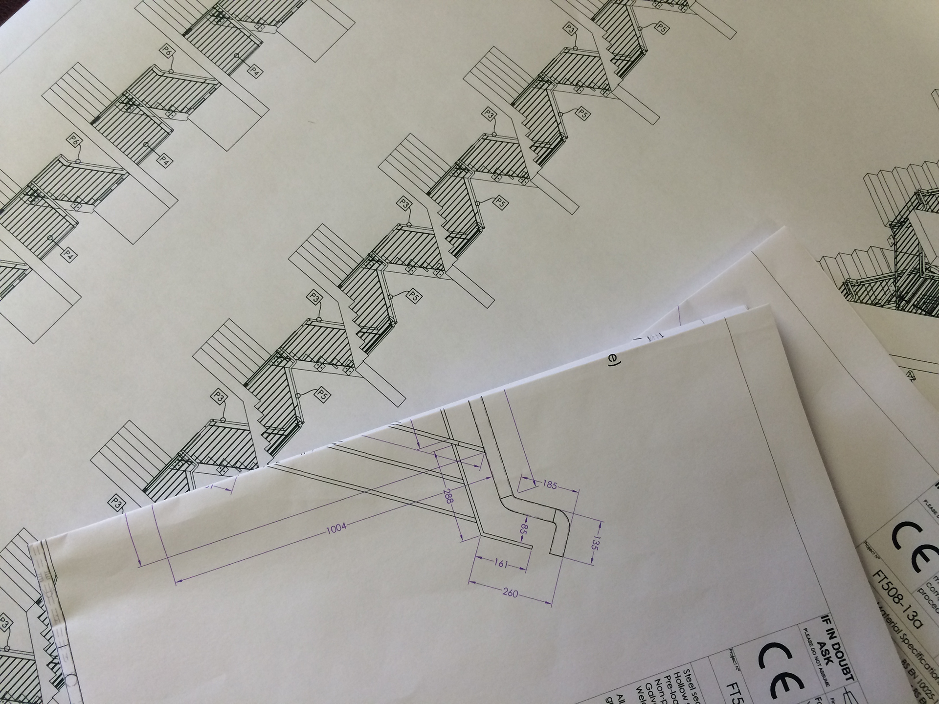
Of course it isn’t all about 3D models & pretty pictures. The whole point of the design stage is to end up with a physical item, and that requires drawings.
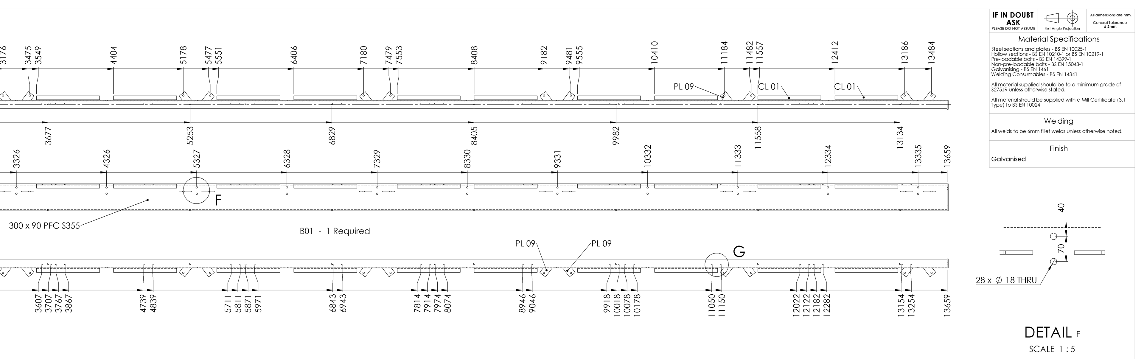
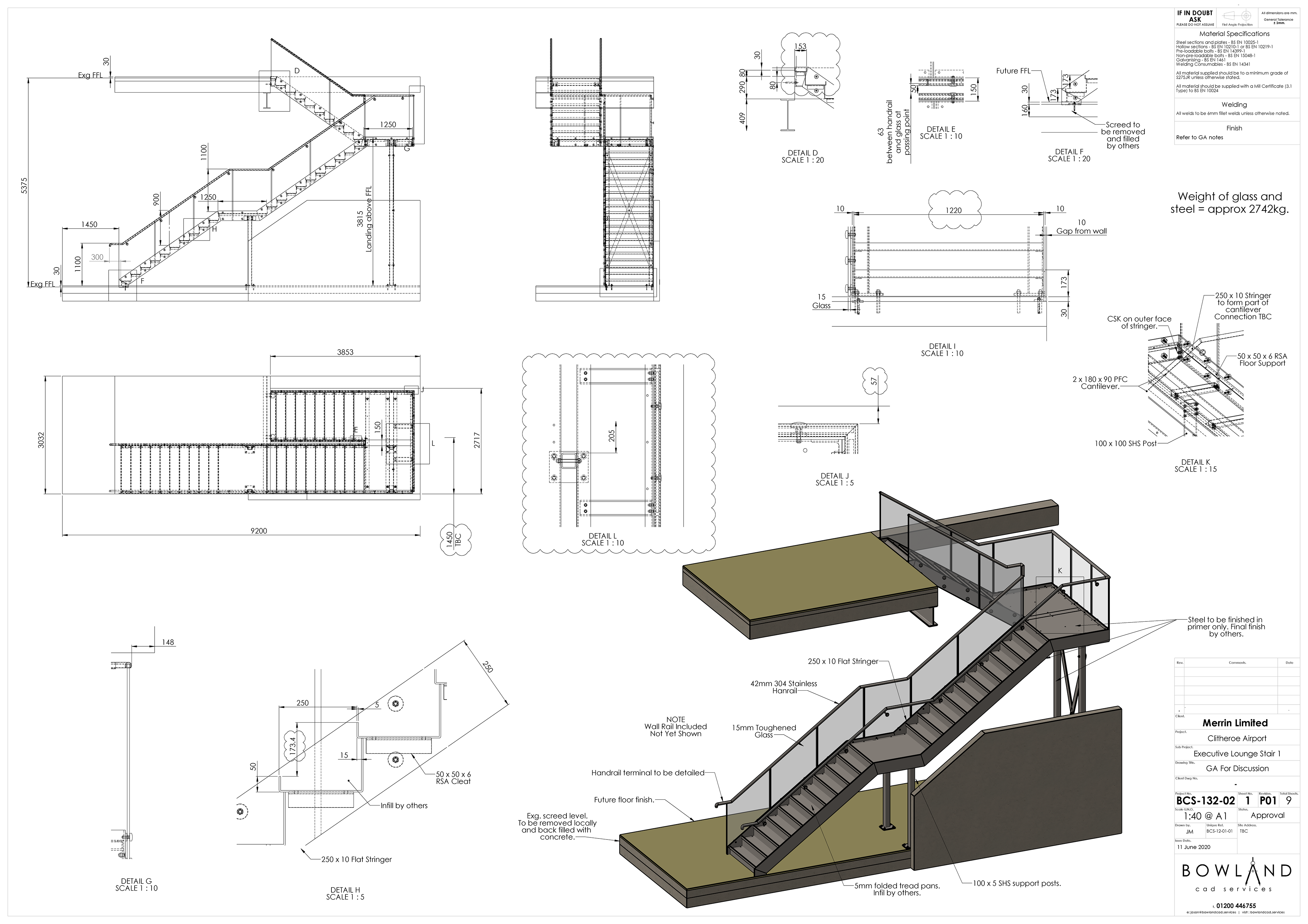
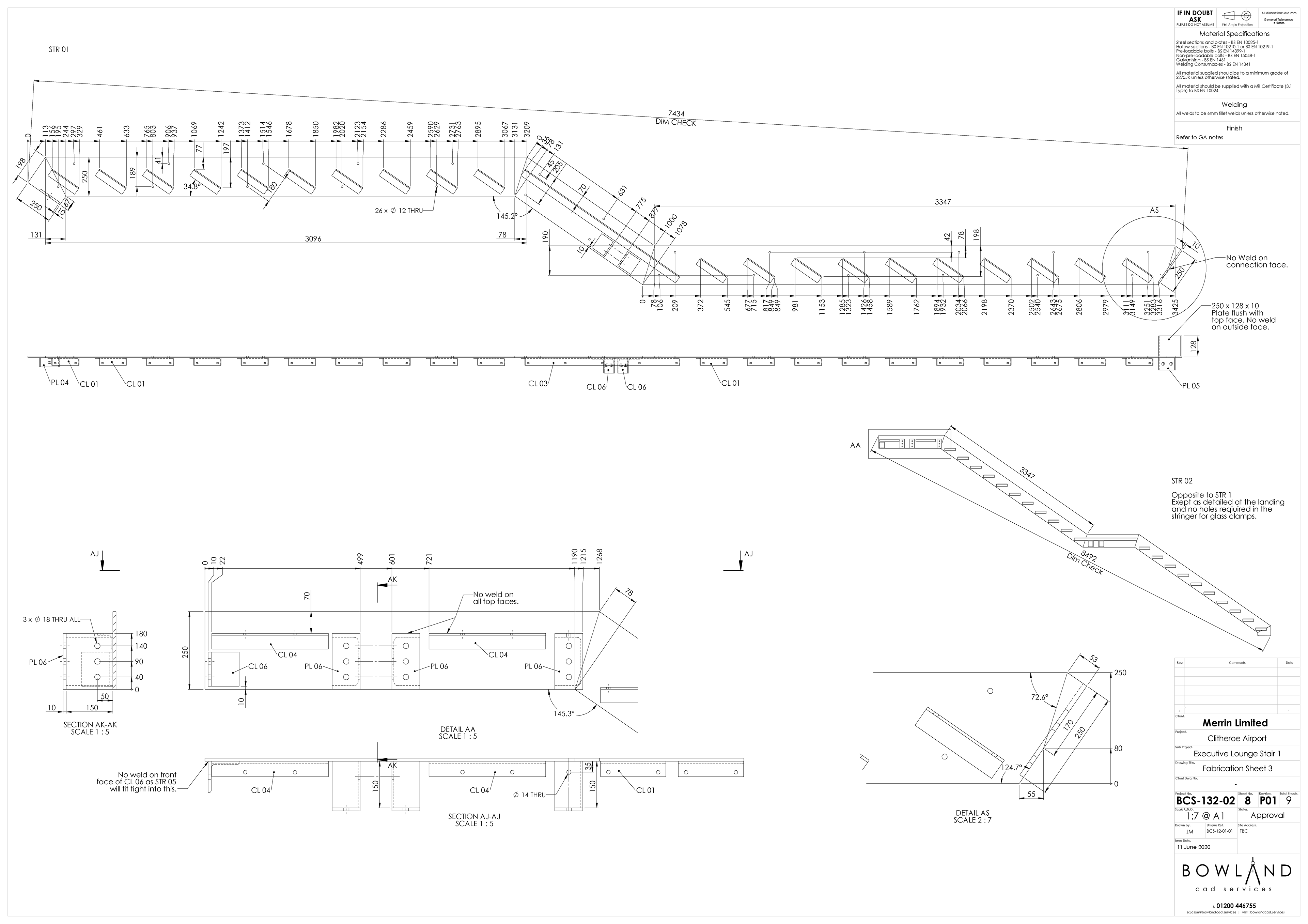
Speaking as a skilled fabrication engineer by trade, I am fully aware of the importance of a clear and concise drawing. I know how an engineer will approach making the parts, and so detail and dimension the drawings in a way that makes them easy to understand and transfer to marking out.
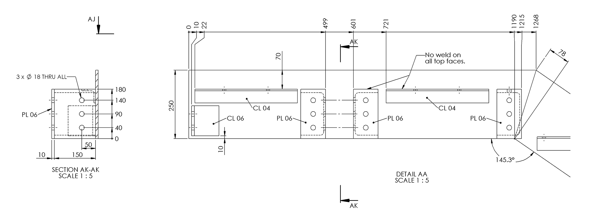
For example, I use absolute dimensions from a datum to remove the risk of the engineer making errors by adding incremental measurements. I know a tape reads from left to right, so I usually dimension my drawings from the left side, where a tape can be easily hooked over an edge. I know an angle can run out a lot over just a few hundred millimeters if it is out by less than .5 degrees, so I add point to point ‘check dim’ annotations to double check angles etc..
There are many small things that make a big difference. I could write pages of them, but the point I am trying to make, is that I know how important the drawings are and take great care in providing all the information needed with as much clarity as possible, meaning that a relatively small investment at the design stage will save time & money during manufacture, and help to produce a better end product.
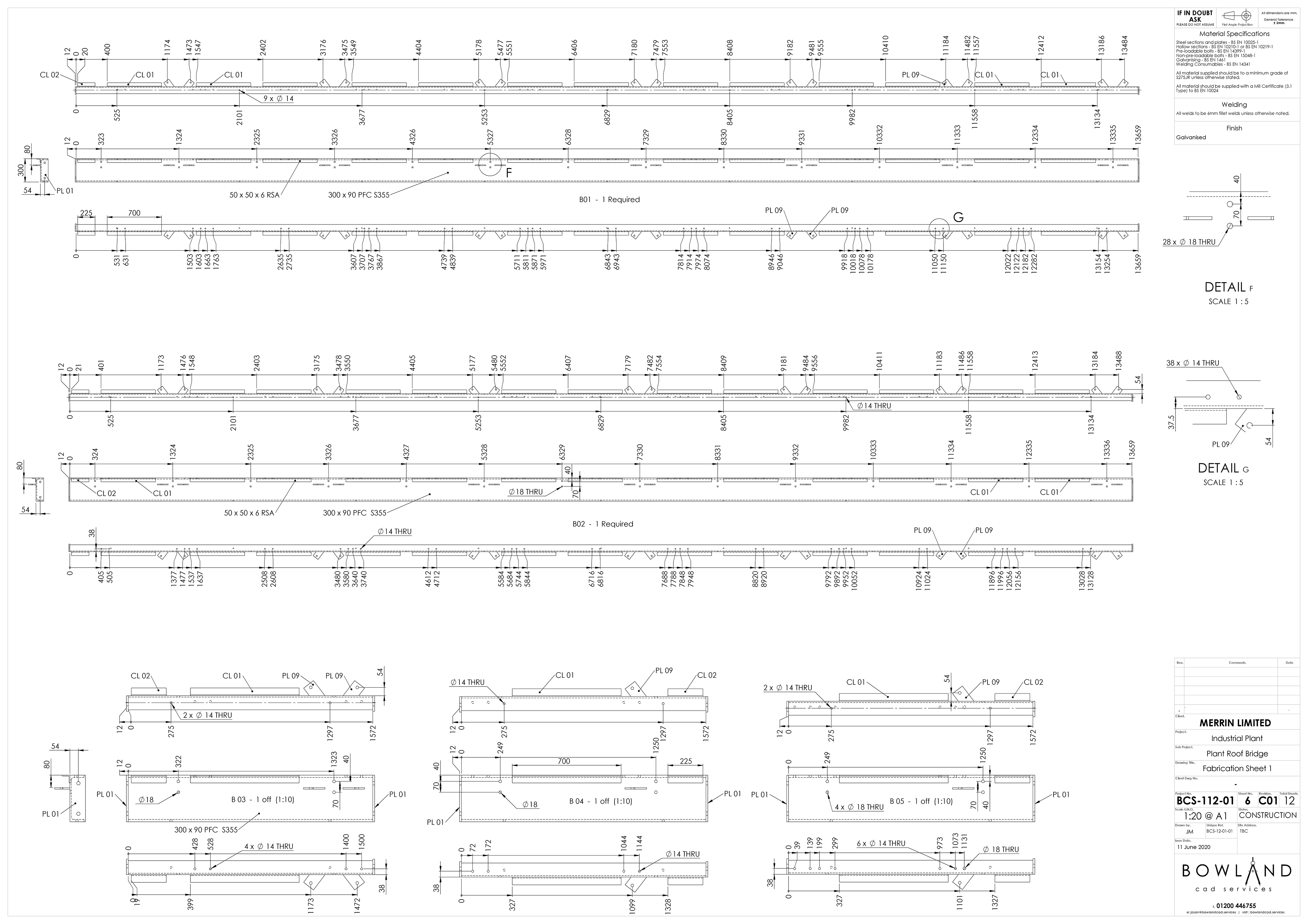
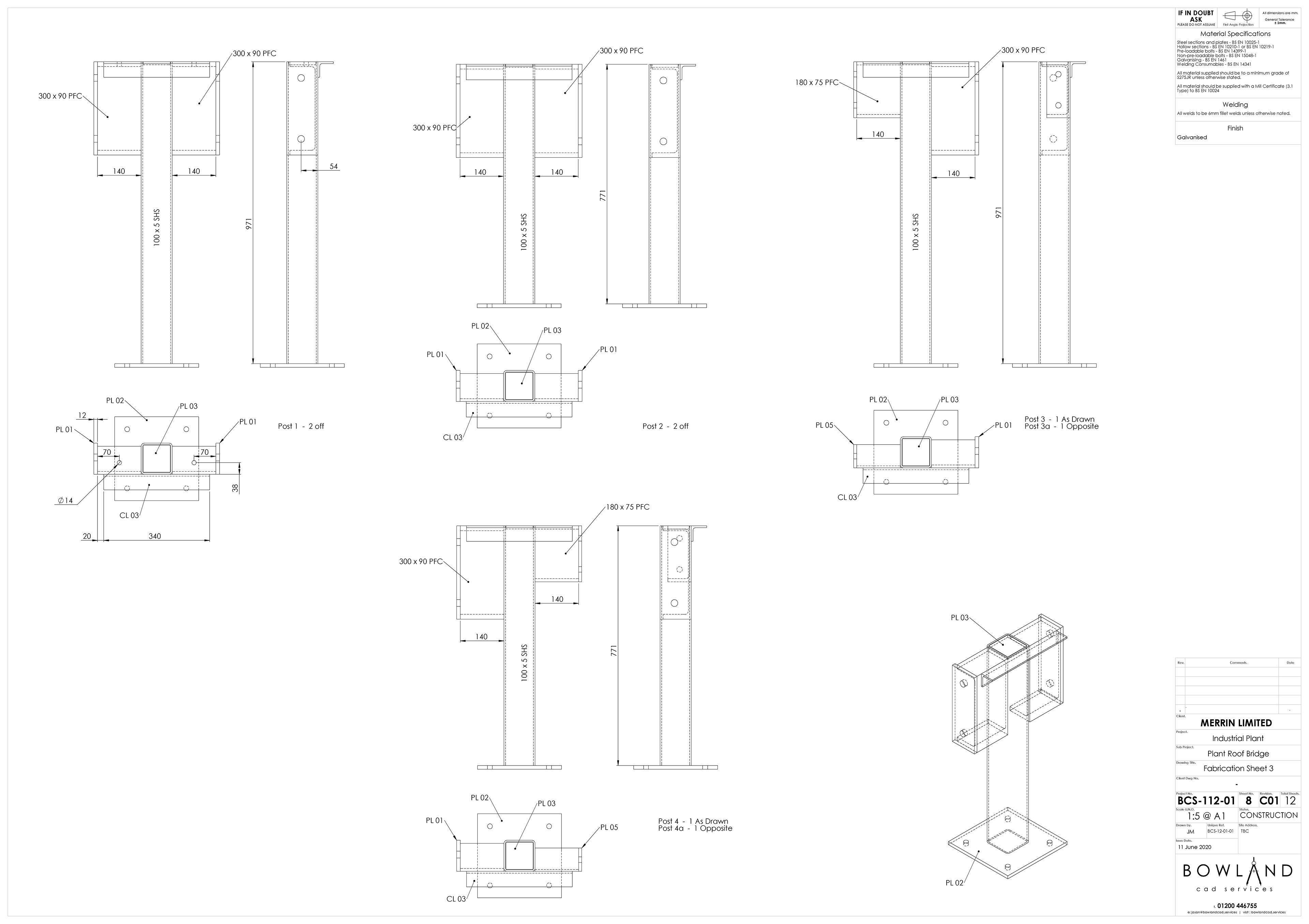
The 2D drawings are created directly from the 3D model, so they are fully detailed, highly accurate and eliminate user errors that 2D CAD were subject to.
I prefer to work in the traditional British 1st angle projection, though I am happy to accommodate 3rd angle projection should your engineers prefer that.
© 2025 Bowland CAD Ltd.